1. Introduction
Some concepts such as “scalability”, “reliability”, “compatibility”, “flexibility”, etc. are so broadly used in commercial literature that its meaning becomes blur. One of these worn-out terms is “redundancy”. This document provides an overview of the redundancy options available with leading IT playout solutions, but draws on standards from academic engineering journals regarding concepts and terminology.
2. Redundancy and Reliability
Redundancy is one of the ways of making a system more reliable. The objective evaluation of its benefits versus the necessary budget is elusive and requires clear criteria and explicit guidelines. The operational consequences of its implementation are also a complex subject since the mere adding of more components — or more units of the same components — does not necessarily increase the dependability of a system, and in some circumstances can even lower it.
The goal of redundancy is to make the system as fault tolerant as possible. Fault tolerance is an emerging quality that derives from the system’s structure and is related to the way this structure reacts to the failure of each element. The system’s reaction is the key to maximising the benefits of the part of the budget invested in redundancy. Good reaction means a greater benefit from the same redundancy (or the same benefit from less redundancy).
The IT-based Master Control Room
Thanks to their long experience working with both conventional broadcast playout solutions and IT-based technologies, Vector 3 were one of the first in the industry to correctly predict the inevitable technology revolution that would occur inside master control rooms. They have led the market in the development of cutting-edge IT-based solutions for the master control room and have helped drive the change, educating the market regarding the reliability and benefits of IT-based solutions with 1000 installations and a large number of channels controlled by their systems worldwide.
While many were skeptical regarding the reliability of IT-based systems, Vector 3, already with many years of experience working with conventional MCR automation systems, proved that with robust and rigorous systems and some strict rules for deployment, it was possible to achieve reliable, frame-accurate solutions with PCs, with multiple advantages over proprietary systems beyond the greatly reduced price-tag.
The role of conventional videoservers was to simply play out video. But Vector 3’s PC-based videoservers made it possible to have one machine superimpose graphics as well as handle transitions and video effects, saving the need for both character generators and mixing desks. Vector 3 was the first to market with an integrated solution, one where routers were the only video equipment required in the master control room. Many big-name companies have since followed suit.
IT playouts work over IT platforms, and the reliability of the latter is a necessary condition for the reliability of the former. The redundancy of the platform and its components (the LAN and the SAN or NAS) is not going to be handled in this document, as there is plenty of literature available on the subject. Thanks to the IT nature of modern playouts, all aspects and knowledge of computer redundancy can be applied. Nowadays most of the computing power in the world is based in clusters, arrays, etc. which use such strategies extensively, so experience is abundant.
Compared to traditional playout solutions, redundancy is where the modern IT-based master control room excels most. Not only is possible to create an endless number of different configurations, but one can also reconfigure the installation, on the fly and as many times as needed, in order to handle different workflow patterns and/or different levels of criticality in the broadcast, depending on the channel and the time of the day, season, programme, etc. Thanks to the connectivity of the LAN and the modularity of the components of the distributed PC architecture, it is possible for any piece of equipment to provide a backup for others of its kind at one given moment and to be used as main for another purpose some time later when there is a more important need to cover. Because in broadcast automation there are only two main types of equipment (videoserver and automation system) the situation is ideal for resources to be assigned dynamically and as often as desired. This extraordinary feature, along with shared backups, is changing the way redundancy is used in master control rooms.
Vector 3’s Vector MultiPlay is the leading playout automation solution on the market, enabling television stations to take advantage of the full range of redundancy options available with IT-based architecture and enabling dynamic redundancy management and monitoring via a user-friendly UI.
3. Types of Redundancy
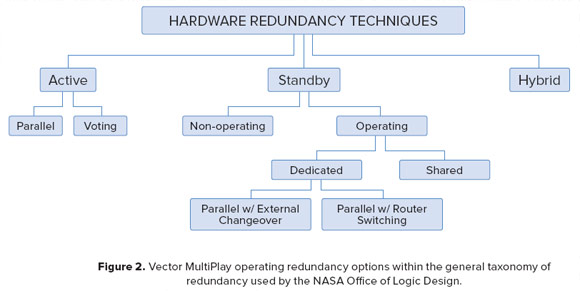
There exist a certain number of different taxonomies to classify redundancy configurations. According to the NASA Office of Logic Design classification system, Vector MultiPlay redundancy options can be grouped under the Operating Redundancy tag.
“Operating redundancy” describes a configuration in which all redundant units operate simultaneously. Typically a sensor detects failures and output is switched to a “hot spare” – a backup unit which is powered up and which can be switched into use immediately after the primary unit fails. Figure 1 shows the basics of operating redundancy. The 2 redundant units in the figure, labelled as A1 and A2, are continuously running in parallel. A sensor in each unit detects failures, and when a unit fails an external controller that receives the information from the different sensors switch the output to the next unit.

In Vector MultiPlay the roles of failure detector and external controller are both covered by Autovia. As explained below, this application, apart from sensing the status of the different channels, processes a set of rules that will determine the future status of the system.
The Vector MultiPlay playout automation system offers a range of redundancy options within the Operating redundancy category: Parallel with External Change-over, Parallel with Router Switching and Shared.
Autovia
Autovia is the upper level of control and the piece of software that unifies the installation by giving structure to its components. Its UI is where the operator decides which MCRs and which videoservers are going to do what (main for each of the channels, dedicated backup or shared backup).
One key feature of Autovia is that its working units are the TV channels as seen by the audience. From an engineering point of view, the only differences between channels are how many hours of live programmes air or if they are part of a network and as such need to have their playlists coordinated. From the point of view of production, the situation is completely different. Each channel has a target audience and a share, and this determines the revenue that goes to the station. Channels with big revenues need to be more protected than channels with small audiences. It is also possible that some channels are more important at some point of the day or week and the producer wants to assign more protection to them during these moments.
In the Autovia UI, the operator can assign and monitor each of the channels, as well as the equipment (main, dedicated and shared with others) that is being committed to its broadcast. Autovia gives a visual status for each channel: green means that it is working fine and all its components have a backup, orange means that is working fine but some of its components do not have backup and black means that there is a gap in the broadcast.
In the event of a failure in one component, Autovia will automatically activate the assigned backup and warn the operator by changing the status (e.g. when one channel starts using a backup component, the ones that were sharing it will turn orange).
Autovia enables redundancy techniques and priority levels to be varied depending on workflows. Redundant resources may be configured to operate in dedicated parallel for key channels at peak viewing times, providing maximum levels of security, and to operate as shared resources at off-peak times. Autovia manages the as-run logs, ensuring that each channel has a single log, regardless of whether backup videoservers or MCRs have been deployed.
4. General concepts
The essential Vector 3 playout equipment for putting a single channel on-air is one VServer controlled by one MCR.
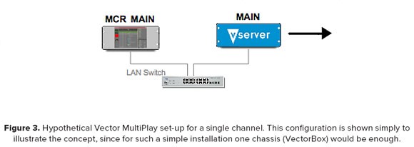
The first approach for creating a fully redundant system would consist of duplicating the channel, i.e. having a second MCR/VServer pair playing the same active playlist in parallel with the main one. If the the failure detector and the external controller are built outside this system, then we have “dedicated redundancy” as described below in point 5.
A simpler set-up would be a single MCR controlling both videoservers at the same time. The videoservers have the same signal at their outputs (video, graphics and effects). Autovia (see the Autovia sidebar) monitors the system components and reacts using simple rules (if “main” fails, put “backup” on-air; if “backup” fails, report without switching). This is done by a crosspoint switch, or a list of crosspoints for different devices if needed, which is sent from Autovia to the DeviceServer.
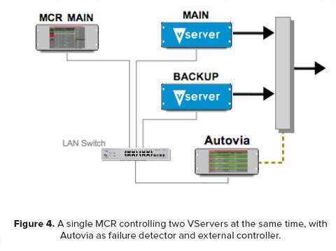
It is not mandatory to have the backup VServer running in parallel. The backup VServer can be “passive” i.e. idle. In this case Autovia will not only put it on-air, but also send orders to the backup videoserver as well as the MCR, which will take control of the videoserver and make it play the corresponding file. In this set-up it does not make sense to configure the system in this way, but this feature is the basis for the shared redundancy explained in point 6 below. In a multichannel scenario, this feature allows Autovia to assign the idle videoserver to any MCR that needs it.
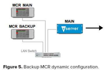
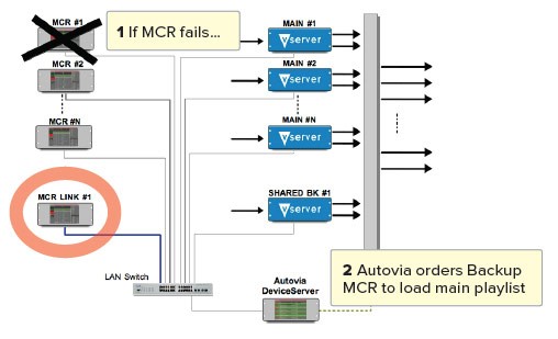
Likewise, we can have a set-up in which we have an idle MCR as shown in the figure below. Autovia is monitoring the components of the system and in the event that one of them fails, it assigns a videoserver to the chosen backup MCR — ideally the same videoserver that was being used so the switch is seamless — and makes this backup MCR load the playlist and resume the broadcast.
5. Dedicated Redundancy
5.1 Dedicated parallel with external changeover
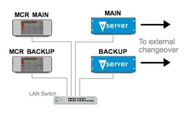
In this configuration, the main and backup videoservers simultaneously output identical video signals in parallel. Any changes to the main playlist are automatically reflected on the backup system. Monitoring of video output occurs downstream of playout, and in the event of a failure in the main signal, changeover to the backup signal is managed externally.
5.2 Single channel dedicated parallel with router switching (videoserver)
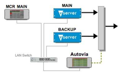
In this configuration there is an MCR controlling two videoservers that are both playing the same signal (video, graphics and effects). Autovía controls the router and communicates the crosspoints of the playlist to the router in such a way that the “main” videoserver goes on-air. In the event this main videoserver fails, Autovia communicates the crosspoints of the playlist so that the backup goes on-air.
6. Shared
Shared redundancy means that a single component acts as backup for many. In IT-based playout, both components (videoservers and MCRs) can be backed up this way as we have seen above. With shared redundancy one can create large multichannel structures where a small overhead of equipment protects the whole facility, giving a very high level of security at the optimum price. Bearing in mind that it is possible to dynamically assign the equipment to different kinds of backup depending on the circumstances of the day, this structure enables users to fine tune the redundancy with great precision (e.g. providing shared backup most of the time and parallel backup of key programming at critical times, or using the backup servers for impromptu ingest, etc.).
6.1 Videoserver
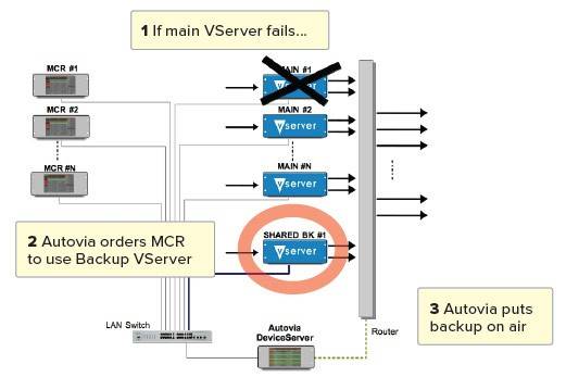
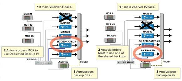
In the figure below, Autovia detects that a videoserver has an issue and tells the MCR (or MCRs if there are more than one) that is using it to change and start using another videoserver. As we have seen in the case of dedicated redundancy, Autovia from then on reinterprets the crosspoints of the router to put the output of the backup videoserver on air.
Since one videoserver is giving backup to many, it does not have the files copied on its local disks. Thus, when it starts playing it will do so from the NAS. When broadcast is stable again, Mediacopier will start copying the files to be aired later, so after a while (depending on the available bandwidth) the backup videoserver will be working as if it were the main.
Once the failed main videoserver is operational again, an operator can choose to put it back on air and can restore the backup server to its previous shared backup configuration from the Autovia UI.
6.2 Multi-channel Shared with MCRs
These same strategies for videoservers also apply to the MCRs. The backup MCR is triggered on the fly by Autovia in the event there is an error in one of the main MCRs. The process includes loading the updated main MCR playlist, thus enabling the backup MCR to take over seamlessly. In the central NAS there is always an automatically updated copy of any on-air playlist.
7. Dynamic Redundancy (Dedicated + Shared)
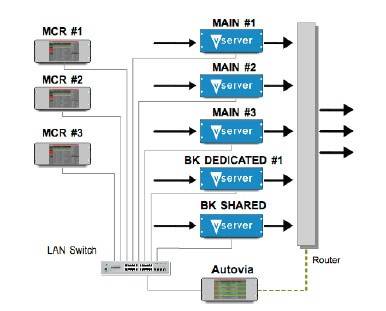
The Dedicated + Shared redundancy configuration makes the most of Vector MultiPlay. Autovia in particular allows the very important channels to be configured in dedicated mode and the less important ones in a shared form. In this way, a backup channel is continuously playing the key channel frame accurately and in parallel with the main one. In case of a failure in the main channel there is no need to load and start the up-to-date playlist; this leads to a faster switch to the backup.
All this is handled by a single Autovia application and configuration.
8. Conclusions
The Vector MultiPlay playout automation system offers a range of redundancy options: Parallel with External Change-over, Parallel with Router Switching and Single or Multi-Channel Shared to optimise resources while increasing security.
Vector 3’s Autovia allows flexible and dynamic assignment of backup components using the TV channel, rather than the facility equipment, as the key concept. The Autovia UI provides operators with a centralised monitor and control point for multiple channels. Autovia enables redundancy techniques and priority levels to be varied depending on workflows. Redundant resources may be configured to operate in dedicated parallel providing maximum levels of security for key channels or at peak viewing times, and configured as shared at off-peak times.
As the Vector 3 solution is an integrated system managing and monitoring all aspects of automation, playout and branding, any error or failure in any part of the playout chain will be picked up and will trigger an alert or an automated recovery response.

